RS3D Missing and no data generated and time gaps

Hey All,

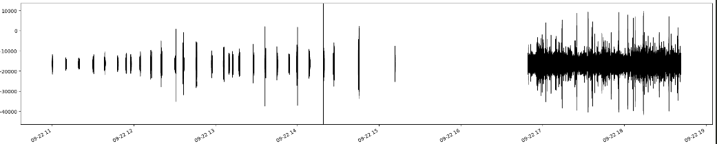
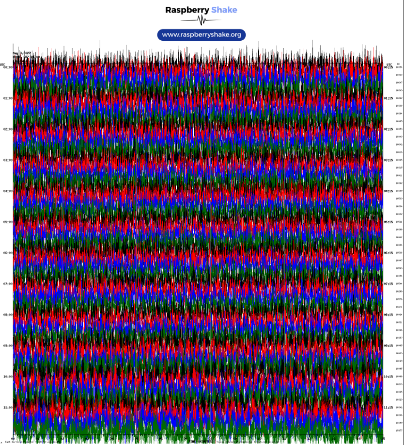
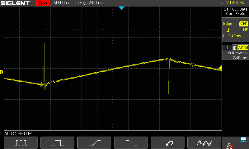
I am trying to find a solution to missing data and time gaps for multiple RS3D’s that we recently purchased. For one of the RS3D’s I followed the initial quickstart guide, and for the time being, I cannot forward the data from these stations, so I do not have data sharing enabled. The RS3D says that it is running, and that it is both data consumer: On and data producer: On. When I select the Helicorder plots on the main URL page, helicorders for today’s date are not being generated after an hour+ after booting up. I was able to connect to the station via Swarm and found that it was barely producing any traces (as can be seen in the image attached). I have attached the logs from this RS3D


RSH.R2146.2022-05-02T16_11_19.logs.tar (2.0 MB)

What surprises me is the fact that I have another RS3D that I had working just fine a couple weeks ago. This RS3D now does not show as a data producer/consumer, and is not producing any data at all. Below is the logs for that system.

RSH.REDAF.2019-02-14T10_56_01.logs.REDAF.tar (1.9 MB)

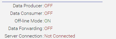
Should probably note that both systems indicate that they have no server connection, but I assumed this related to data sharing with RS servers. If this is incorrect, how do I fix this issue?

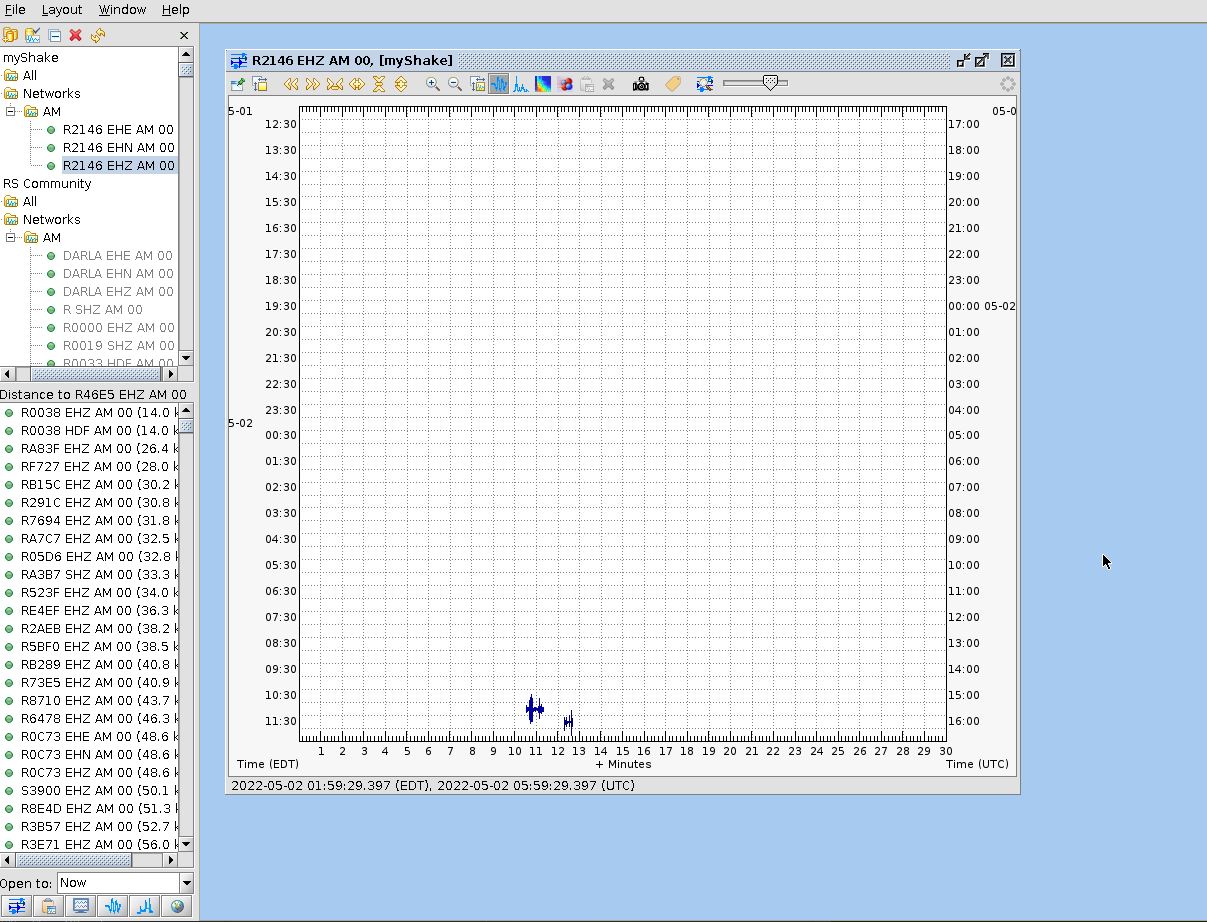
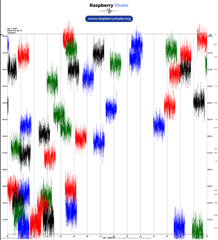
EDIT/UPDATE: The second RS3D (REDAF) has started to produce data visible in SWARM and there doesn’t appear to be data gaps in the timeseries as there is with R2146. REDAF also maintains no server connection so that does not seem to be the limiting factor.

1 Like

More updates now that I’ve allowed both systems to run for a days time. As suspected, there are significant time gaps in the RS3D snR2146, but the snREDAF has continuous data. I unfortunately have two other RS3D that are having similar time gap issues Here are plots of the helicorders for the good and bad RS3D. Not sure how to rectify this issue with R2146 and any help on diagnosing the issue would be greatly appreciated.


1 Like

More Updates:
I mentioned before that we had several RS3D. We have needed to fabricate our own power cables to reach installation sites that we intend for these stations to go. These lengths extend from the RS3D’s at 5, 10 and 15 m. We are using a 18 AWG power cable for these runs which we thought would result in minimal power loss. After testing, what I found is using the provided RS power adapter that outputs 5 V DC 3.0 A connected to our own cables, that the a 5 m length run was able to power up the RS3D’s without issue with continuous data production. The 10 m length run resulted in intermittent data production, and a 15 m length cable resulted in the RS3D remaining in “booting” mode in the rs.local/ URL page. Thought this might be useful information for anyone following this post or that may have similar issues in the future.
As an aside, it might be a good idea for the development team to figure out a way to improve the State-Of-Health page for the sensors. It would be helpful to not only know the system temperature, memory usage % and timing, but also the current voltage and power draw of the system. Also, having some idea of how many satellites are being tracked by the GPS would be nice. Something to consider.

2 Likes

Hello jpschmidt8,

Thank you very much for the extensive reports, provided logs, and screenshots. They have helped in getting a good sense of what was possibly happening.

We have had, in the past, similar instances of data interruptions in the helicorders produced by the Shake itself, that indicate that the issue is located within the Shake, and it is likely independent from any data transmission fault, present or not.

In these instances, the “culprit” was almost always found to be in missing or malfunctioning power supply, which can be also caused by longer-than-usual power supply cables/lines. In this cases we recommend to acquire more robust power supply units and/or cables that are able to deliver a constant 5.1V 2.5A to the Shake.

When this does not happen the issues can be multiple. Permanent BOOTING status, gaps in data recording (as you have seen), Shake that does not even boot, corruption in the microSD card, and others.

Regarding your suggestions, thank you! We are always looking forward to seeing what our users actually need and we try to implement them as soon as we can along our work pipeline.

I will open a ticket for our software team so that they can take a look at this and see what can be done for the future Shake OS releases.

2 Likes

Quick question,
does anyone on the support team know if there is internal power regulation on the RS3D and 4D’s? The easiest solution for us would be to just buy a new AC power supply adapter that feeding a higher voltage of 7.5 or 9 V to compensate for the power loss along the run, instead of the 5.1V that the raspberry pi AC plug came with. So really, I guess the question is what is the maximum voltage that the system can withstand? I suspect that if the internals of the RS3D and 4D are unregulated systems, then they would likely only handle +/- 0.5 volts outside tolerance (as far as I am aware). Any information on this would be extremely helpful.

See here: More power to your Pi - Raspberry Pi

I would probably think about using a 12v to 5v regulator maybe like this:

right alongside the Shake device, and a 12v PSU.

I use something like this to check voltage at the actual input port of devices:

We recommend not letting the voltage drop below 5.0V and not going above 5.2V, for optimal performance. This has to be paired with at least 2.5A current.

If I remember well, the Pi is engineered to work at 5 V, plus or minus 5% (4.75 - 5.25 V), but you can easily check the datasheet for your Pi model on the official website to be sure.

If you need any other info that we can provide, feel free to ask!

Hey PhilipPeake
Thanks for the suggestions above. I do want to check though (pardon my ignorance), it looks like this converts 6, 9,12, 24V to 5V, but does it also boost/maintain a 5A output? Let’s say I purchase a AC power adapter that outputs 12V 3.0A, would this convert strictly reduce the voltage to 5V and maintain 3A from the AC power adapter, or would it increase it to 5A? As the optimal level for the RS3D’s are at 2.5A, would having double the amperage be damaging to the instrument?
For example, would swapping out the RS power adapter supplied with something like this work with that step-down converter?
https://www.amazon.com/MEROM-Universal-100-240V-Switching-Transformer/dp/B08P4H27L9/ref=sr_1_1_sspa?crid=2A4K18ABADN26&keywords=ac+to+dc+power+supply+12v+3a&qid=1651693152&sprefix=ac+to+dc+power+supply+12v+3a%2Caps%2C81&sr=8-1-spons&psc=1&spLa=ZW5jcnlwdGVkUXVhbGlmaWVyPUE0V0E1R1BTUVZCSUYmZW5jcnlwdGVkSWQ9QTAwNTExODUyUURLTDZBUkQ4NTdFJmVuY3J5cHRlZEFkSWQ9QTA1OTIzNzczVlpNTk9JOUxSNDNEJndpZGdldE5hbWU9c3BfYXRmJmFjdGlvbj1jbGlja1JlZGlyZWN0JmRvTm90TG9nQ2xpY2s9dHJ1ZQ==

1 Like

That is a common question. The current rating of a power supply is the MAXIMUM current that it is designed to supply.

When selecting a PSU, look first at the voltage. The voltage needs to match the requirements of whatever you are intending to power with it. If your device needs (say) 9v then you find a PSU that delivers 9v. The device will draw some current at 9v - the power supply doesn’t force the current into the device, in the most simplistic view, it is the voltage that forces the current. The poser supply just has to be ABLE to deliver the maximum current that the device might need. Most devices don’t draw a fixed current, the current changes depending on a lot of factors, including what the device is doing. That is why, for example, the current demand of the Raspberry-Pi is specified as a range: 2.5A to 3A.

If you choose a PSU with a current rating exactly matching the requirement of your device, you will be running it at 100%, all the time. Instead, aim at something that can supply just a bit more current than you need. That way, your PSU is running at less than 100% capacity all the time, and will probably last longer.

The first PSU drops the voltage to (say) 12v. The second works in exactly the same way, but it is designed to work from 12v DC rather than 120/230v AC. It still delivers a steady 5v. Being closer to the R-Pi there is less voltage drop on the 5v line. As long as the first PSU can supply (say) 5A to the second, which can deliver up to 5A @ 5v to your R-Pi, all will be fine.

It can be instructive to check out your cables with the USB in-line voltage/current device I pointed to previously. I had a similar problem with an R-Pi. I has spent a lot of money on good quality USB power cables (at least, that is what the Amazon ad claimed…). Plugging the dvice in-line at the PSU end and seeing 5.2v was ok, plugging it in at the R-Pi end, and seeing 4.8v was not. I don’t know what size wire was actually in those cables, but it was most definitely NOT what the ads claimed - very pretty cables, but useless.

The proper engineering solution is to have the regulated PSU as close to the device it is powering as possible (particularly at low voltage, high current).

1 Like

Hey PhilipPeake,

This is all great information and I appreciate you sticking around and helping me work all this out. I do have one concern though, and if you’d indulge me, I’d appreciate your input/advice.
To describe the current setup I am working with in a little greater detail, I am planning on burying the RS3D below grade in a small water-tight PVC box at my installation site. With this power loss issue, my initial thought was to do as you suggested and purchase a new power supply that converts from AD a 12V 5A DC current that would then run down the length of my 15 m cable to where I’d bury the sensor. I would install the buck converter inside the enclosure that holds the sensor to step the 12V down to 5V and run a very short cable inside the box from that convert to the RS3D. that way I could protect the converter from the elements.
In looking around on the internet, I noticed some individuals complain that buck converters generate a large amount of RF noise, which would likely degrade my signal. I was thinking that I might be able to counter the majority of the RF noise by wrapping the buck converter itself in some loose fitting foam, and then wrapping that foam with aluminum tape to act as a RF cage of sorts. I was just curious if you might have thoughts on this approach, and see if you might have suggestions on how to best counter the RF? If not, then no worries, I greatly appreciate the help you’ve provided on this topic nonetheless.

1 Like

RF noise is an unavoidable consequence of the way that buck converters work. A good design will minimize this, and will include some filtering. The problem is that the RF is caused by very narrow “spikes” on the output. Because the spikes are so narrow with fast rise and fall times they have harmonics often reaching into the GHz region. The power levels of this noise are quite low, so only affect sensitive equipment in close proximity.

Now would this noise affect a R-Shake? It’s pretty low level, and well above the frequency range being measured. The board that amplifies and digitalizes the signal from the transducer(s) is known to be susceptible to RF, but typically relatively high levels. I have seen this with mine, but only when running 1kW of RF within a few feet of it!

My guess is that you won’t have any problem. If you want to try a bit of screening, I would go more for a metal box (Aluminum) and a bit of filtering on the 5v side - simplest would be a ferrite toroid with the output wire wrapped through it a few times. That would reduce any common-mode signal on the output wire, but wouldn’t really do anything for a differential signal.

I would be a bit wary of wrapping it in foam. These are very efficient devices, but they do still dissipate some power, so I would tend to allow a bit of air flow - that was mostly why I said use a box.

Of course, none of this may be necessary… I suspect not.

The alternative would be a linear regulator. They have dropped out of fashion because of the much lower efficiency, but they are silent as regards RF. I don’t know if you can actually buy these pre-built any more, but you could build one …

BTW, I think that it is 99% certain that the R-Pi PSU actually uses a buck converter.

I have just placed an order for a " UCTRONICS DC 6V 9V 12V 24V to DC 5V 5A Buck Converter Module" from Amazon. If I get time this weekend I will take a look at the output with an oscilloscope, and a spectrum analyzer, and also see if I can pick up any radiated signal. I have been meaning to do this for a while - I have an R-Pi running some A-V software (Kodi) on the back of my TV. The power lead is not tucked away as cleanly as I would like (too short). If I try to extend it, the voltage drops too low and the R-Pi begins to complain and do odd things.

2 Likes

Received my 5v buck converters from Amazon.
They look well made, but let’s see…

Applied 12v to the input, and a load to draw 3A form the output.
The output voltage, at 3A measures 5.2v (actually 5.196v), so that seems ok.

These things work (in the simplest way) by switching the input supply on, to charge a capacitor across the output. As the capacitor charges, the voltage on it rises. When the voltage reaches just a bit over the target voltage the supply is switched off. The load draws current from the capacitor. As its voltage falls, when it drops to just a little bit below the target voltage, the supply is turned back on to re-charge … this typically happens many times per second.

So what we expect to see is (in our case) 5v with a bit of “saw-tooth” ripple on top of it. Also, because thw switch on and off is so fast, there is going to be a small spike as the “switch” opens and closes. Any RF interference comes mostly from these spikes, so we hope not to see hue ones…

First look:

The “saw-tooth” is clear. But it is not very big. The vertical scale is 20mV per division, so the saw-tooth “ripple” is ~20mV. The horizontal scale is 2 micro seconds per division. This is very low level. You are more likely to have bigger signals from your local AM radio stations.

Now, the switching “spikes”. You can see them pretty clearly where the supply switches on and off.
Taking a closer look:

There is a tiny bit of oscillation, but low amplitude, less them 20mV. The switching spike itself is a bit bigger, maybe 30 to 35mV and one complete cycle of the pules (if it had one, the second half of the cycle is truncaed) would be around 50 nano seconds, which is ~20MHz.

But again very low level.

I don’t see these causing any problems powering an R-Pi or R-Shake.

1 Like

I had a bit more time, so I spent a bit more time getting cleaner oscilloscope traces:

Those spikes look more like I was expecting…

Next I did some quick tests to try to determine how much RF interference it was generating.
The first test was a rather simple one, taking a radio (Sony SW receiver) and holding it close to the PSU.
On MW frequencies there was an increase in background noise once the receiver got within about four inches of the PSU. Tried on a couple of successively higher SW frequencies - same thing. I am not surprised, as I mentioned previously, the fast switching generates signals up to GHz frequencies.

Next I tried making up a small probe of a few turns of wire connected to a spectrum analyzer and too a look at what was picked up with the probe about half an inch from the PSU:

Those signals are pretty low. They vanish if the probe is moved more than a couple of inches away.
As expected, applying a 3A load increases the level of the signals generated, but it still remans pretty low.

Increasing the frequency range, moving the top frequency out the 5 MHz, then to 20 MHz shows the harmonics continuing, with little if any change in amplitude. Again, as expected.

===========

Some practical stuff:

These PSUs don’t have any mounting holes, so how to mount them securely? Velcro and double sided tape seem like common solutions, and should work ok. However, the purist in me doesn’t like this, so I did a bit of searching around. The best solution seems to be some mounts for edfe or corner sold by Adafruit, and cheap enough at $2.95 for a pack of four. But the postage costs put me off.

I found the Chinese manufacturer, and they sell them for ~30c each. But you need to buy a minimum of 1,000 to get that price.

Finally, I found the same thing sold by DigiKey:

https://www.digikey.com/en/products/detail/essentra-components/TCEHCBS-4-01/368159

$0.29840 each if you buy 25, and postage at $4.99 (Yes, I only need 4, but they seem so useful that a few spares seems like a good idea).

2 Likes

Hey @PhilipPeake, This was great information. Ended up purchasing a handful of those buck converters and are currently testing them out to see if I can get them to work. Tested the output voltage at the sensor end and it looks like I’m getting 5.22 V out at that end, which is a good sign. I have connected it to the sensor and it on the 15 m cable, the sensor comes up and no longer is in a constant “booting” mode as before. The data consumer/producer flags are both ON and i can see data streaming in SWARM and it is continuous! Looks like the last thing I have to tackle is mounting that buck converter, and I appreciate your input on this front (didn’t even have to ask, man you’re good :wink: ).
I did have a question/comment though for the RS team. It relates to the RS booting up and the data producer/consumer situation. for my most recent tests, I had to move locations to do the modifications to the 10 and 15 m cables to accept the new plug adapters since I couldn’t user the RS supplied ac/dc converter. This new office doesn’t have ready internet access, and I was doing some initial testing with the RS3D’s connected to a router and making a small LAN to then view the data on my laptop. Trying to test my new power setup, I tested 3 RS3D’s without active internet to the router, and all 3 RS3D’s powered up, but never transition to data producers/consumers. This made it hard for me to verify my new setup was working since there was no data to view.
I might make a suggestion to the team if possible to make it so that the RS3D can at least produce data without an active internet connection. I suspect this is the issue I was encountering because once I was able to finally establish an active internet connection to the router (and therefore the RS3D), the RS3D finally transition to producing data I could view in SWARM. I waited several hours trying to figure out why these instruments weren’t producing data and I was worried that they might have bad SD’s or something. If there might be another reason why it took so long for the RS3D’s to make that transition, please let me know, that would be useful information in the future. :slight_smile:

1 Like

Glad it’s working for you.
BTW, I received some of those board mounting pillars I mentioned – unfortunately, there isn’t enough of a border available on the converter to even use those. So it looks like its going to be double sided tape …

I bought some small plastic boxes to put them in:

Cheap and cheerful. Will need to be careful in drilling the holes for the cables, and will probably wrap tape around to hold the lid in place.

There is a way to produce data with no internet connection - see what I think is called “Disconnected Mode” in the manual. As far as I can tell, it skips the start-up requirement that NTP be connected and running to have the time set. Of course, you need to ssh into the device to set the time as accurately as you can, but for testing purposes (or demo purposes) it’s probably fine.

One other note: I did read one comment that the capacitor on the output “was disconnected”. Well, since these work by charging that capacitor up to the required voltage and keeping it there, without it, it won’t work well (like at all…). With all the messing around I was doing, I managed to “disconnect” one side of that same capacitor. These are surface mount components, so they have tiny tabs sticking out which are flow-soldered to the PCB. The soldering only holds around the edge of the tabs, so apply much pressure to the capacitor and it is fairly easy to lift that tab. Fortunately, it is pretty easy to get to, and re-solder with a fine-tip soldering iron. Shouldn’t be a real problem so long as these are not handled a lot.

An original capacitor tab:

and a re-soldered one:

2 Likes

Thanks for point this out. We actually had one of these come loose in the field while we were installing, and I immediately recalled you pointing this out, and low and behold, it was the issue why that station wouldn’t start correctly. Thank you for all the help! I will say your solutions helped us get 6 RS installed the last few weeks. :slight_smile: Cheers!

2 Likes

Glad it was some help. I used one of these to solve the problem of powering an R-Pi running KODI which sits behind the TV. With a 5v wall-wart PSU the ones that work come with wires really too short for this application, and end up stretched fairly tight between wall socket and Pi. Extending the wire doesn’t work, the voltage drop is too much. So I bought a 12v PSU from Amazon, and placed one of these a foot or so from the Pi.

Perfect … I can now easily run the wires where I want them.

I only had one capacitor come loose (the one in the photos). Unless you know to look for it, it is not easy to find.

2 Likes

Hello,
I appreciate the posts on this thread, as I seem to be having a similar issue. I am using the original power supply that came with the Raspberry Shake (RS3D v9 1009), and I am getting similar issues. I am wondering if this is because I have installed a USB storage drive and a wifi dongle (I should also mention that the GPS antenna that came with the device is also plugged in). I installed the wifi dongle following these steps and the USB storage drive following steps here. Everything seemed to work alright (though currently the fars-robotics site seems to be down, so I could not get the wifi dongle driver installed on one of the shakes). Here are a couple examples of some data that I am getting back, one from obspy and one from a plotting function I put together (red bars are data gaps in the second image):


and
.

The gaps are not always regular intervals like in these two images, but they often are.

Could the USB Storage and/or dongle be drawing extra power and causing this issue?
Thanks,
Riley

1 Like

Hello rbalik,

From their appearance, this could be related to a power supply issue. However, to be sure, could you please download the logs (instructions can be found here, if needed: Please read before posting!) and post them here?

They will give me a more in-depth insight into what is possibly going on.

Thank you.

Hello,

Below are the log files. This is from a different shake than I sent you the images from before so I am also including images from this shake for a semi-random two-hour time period (this seems to be happening fairly consistently) from the N component mseed file.

RSH.R8177.2023-09-22T15 46 16.logs.tar (6.8 MB)

I think I remember in the past there was a command through ssh that showed some of the logs (I feel like I remember seeing a Low Voltage warning/output). Is this correct, is there a way to see that kind of warning message through ssh? Just out of curiosity, would it also do the same for temperature?

EDIT:
For more context: I am using this in offline mode with the GPS antenna connected as well. I have turned off the onboard wifi, but with this shake, I have not been able to get the wifi driver for the currently-plugged-in dongle going (see previous message). The shake I am sending the logs from was plugged into the AC power supply that came with the shake. Now that I am looking more carefully at the rs.local page, I see the Data Producer/Data Consumer services are off, though I did nothing to do that that I am aware of. I am pretty sure these were on earlier today when I first drafted this message.

EDIT EDIT: the Data Producer/Data Consumer services are back on again 5 minutes later

image

EDIT EDIT EDIT: It looks like I was using an AC power supply from an earlier model (v7) that had an amp rating of 2.5A. That same model does the same thing with the 2.5A power supply (with the extra accessories) too, though. I switched my v9 shake to the power supply that came with the v9 (3.0A) and for the past 2-3 hours, it that seems to be working fine as far as I can tell. I switched the power supply a little after16:00 (09-22 16) in the image below. The end of the plotted line is the end of the datastream when I downloaded the data, not a gap as far as I can tell.

2 Likes