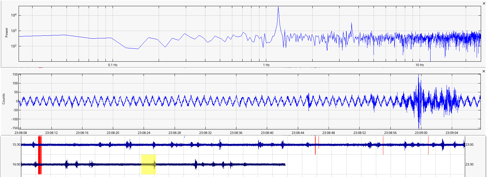
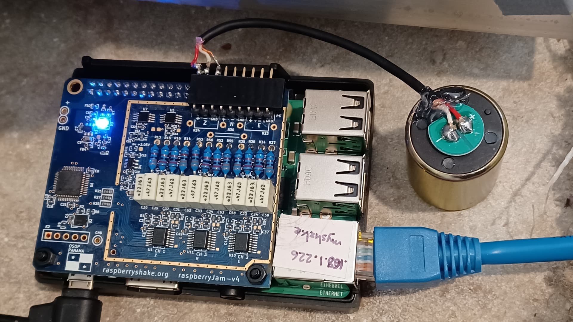
I’m not sure if this is a product anymore, but some time ago I bought a “Raspberry Jam” board. The PCB is labelled “raspberryjam-v4”. I recently pulled it out of my projects box to use it on a Raspberry Pi 3B+ board, with a 4.5 Hz vertical geophone (measured R = 380 ohms, with an added 680 ohm shunt resistor for some damping). I notice that the measured signal from this (Z channel) has a significant and constant-amplitude narrowband signal at 1.2 Hz and it does not change over some hours. The normal noise of nearby road traffic appears superimposed on this signal, so the geophone is otherwise working as expected. When I tried this same geophone in the same location, with a different system (my own ADS1256 ADC board) I did not observe this ~2 Hz signal. I tried powering the Pi with a standard 3A 5V USB supply, and also a 2A battery powerpack so it is DC-isolated from ground, but observed no difference to this constant 1.2 Hz signal. The Pi is connected to wired ethernet, so I am not using wifi, and AFAIK there is no RF enabled on the Pi at all. Any thoughts about the source of this signal?
It occurs to me that the last time I tried using the R-Jam board, it was probably configured for a +/- 10V input signal, and the geophone of course is a uV to mV signal source. I have not changed the resistors recently, so there is likely a dramatic signal attenuation happening. However, that does not explain a narrowband 1.2 Hz signal.
EDIT: ChatGPT (apparently) has read and absorbed all the discussion on this seemingly obscure subject on this board’s forums (something I had not done over the past several years, while focusing on other projects). Not just that, but it comes up with legitimate looking customized code examples (C or Python) to construct new, higher-rate sampling code for the MAX11200 chips on my Jam-v4 board, that it implies should fix my 1.2 Hz tone issue. I haven’t tried running those yet, but if the AI’s code works, this seems pretty brave-new-world-ish to this grey-haired programmer.
Hello jbeale,
All the resistors are sensor-specific, as you have surmised, and have to be customized to suit the specific sensor that is attached. Probably, something in the entire configuration is “mixing up” and generating that unusual (but cool to look at!) signal.
If you want to be sure about the internal WiFi being deactivated, you can do it in the boot config:
- SSH into the Shake
- execute
sudo nano /boot/config.txt - paste the following
dtoverlay=pi3-disable-wifiin the file above - save the edits and then reboot the RJAM
As the RJAM was discontinued years ago, we have compiled all resources here. Maybe it can be of help.
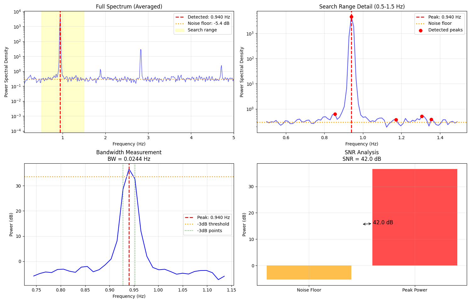
Just in case of interest, I wrote a program to lock onto this very narrowband signal, in this case near 1 Hz and remove it from the other seismic data. I managed a surprising amount of removal, over 30 dB (from a channel with no sensor attached, just resistors):
...
Block 1662/1664: Δf_est = -0.993 mHz, delta_f_external = 0.213 mHz
Block 1663/1664: Δf_est = -0.966 mHz, delta_f_external = 0.154 mHz
Block 1664/1664: Δf_est = -1.123 mHz, delta_f_external = 0.091 mHz
Interference suppression: 31.0 dB at 0.93994140625 Hz
Original power at target: 4.25e+04
Cleaned power at target: 1.20e+03
Achieved 31.0 dB suppression using simple_continuous_tracking method
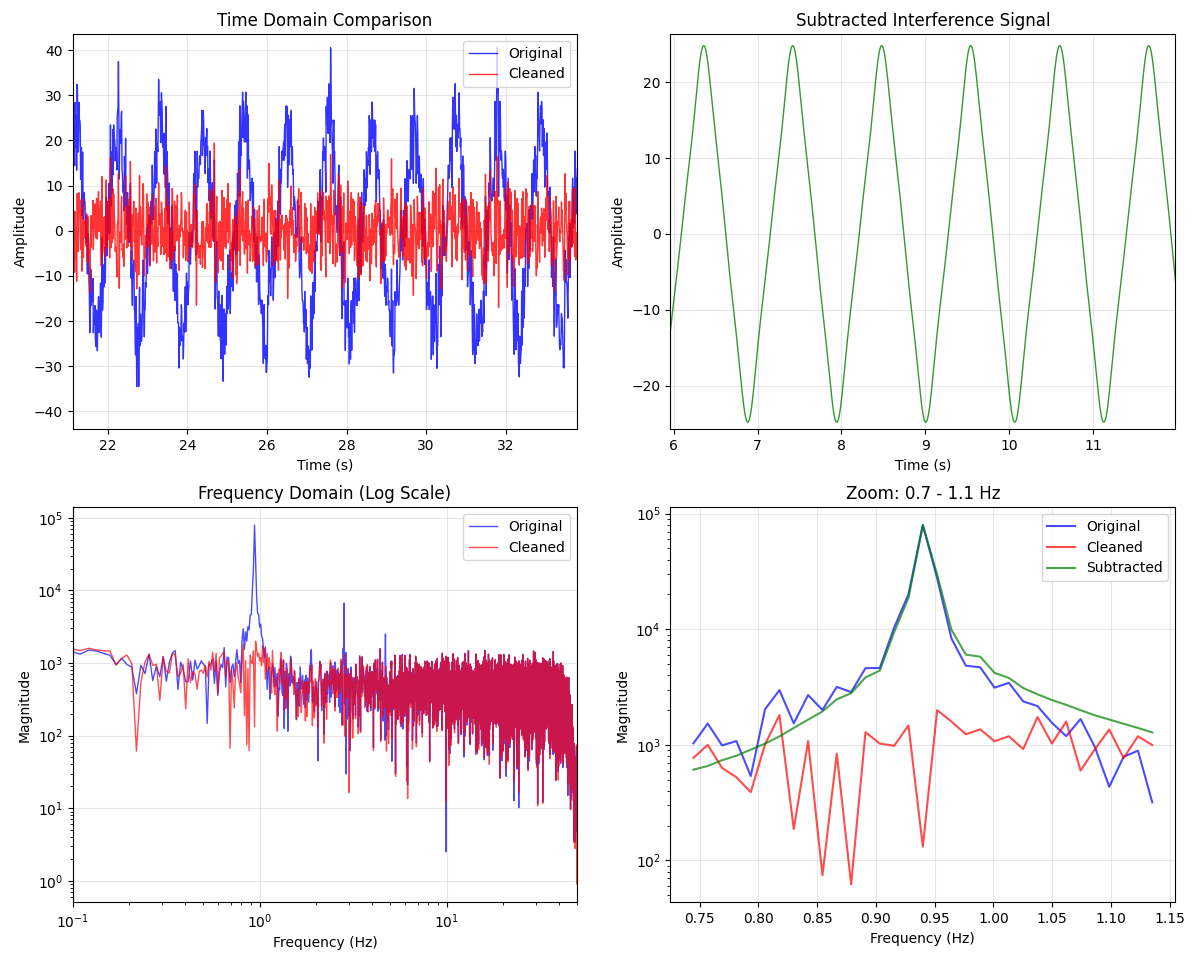
I did a lot of back-and-forth with AI assistance to develop the algorithm, and some hand-tuned parameters likely specific to my setup. Supposedly these ideas are also used in existing commercial fixed-tone-cancelling systems. This was in some sense an easy target as the interference frequency varies only by milli-Hz, and the amplitude is likewise rather stable. Here is the code: seismo/rjam-clean.py at main · jbeale1/seismo · GitHub
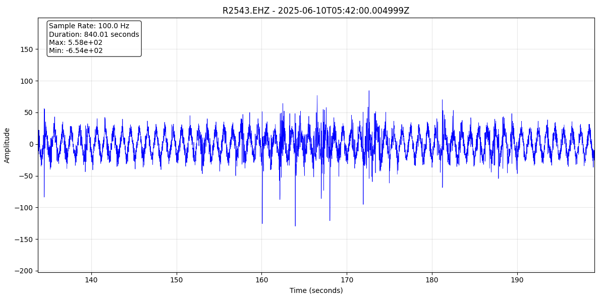
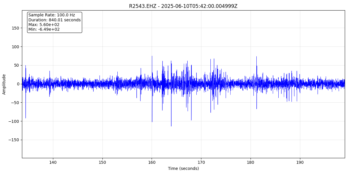
Have a look at these before-and-after traces from a channel with a geophone attached. The interfering signal is really removed, leaving some small high-frequency seismic signals much more apparent (in this example, mostly just my own footsteps and other manmade noise).
Oh my, this is an amazing work jbeale!
Thank you for sharing it with everyone in the community. It could be a great starting point for others to customize it to work for their specific cases.
Love it!
Glad it seems interesting- I have to say, it is a brave new world now. I had a lot of back-and-forth with it to work on some issues, but essentially 100% of that code was written by the AI tool (Claude 4.0). I have a technical background and software is my day job, but the AI tool came up with the PLL idea based on my brief, not-very-technical description of the issue. I suggested the separate amplitude tracking after it had already implemented the separate slow phase tracking loop. It constructed all of the presented graphical displays, without me even asking for them.
yep… it will think ahead of you, when you lead it there