I am putting together my own layout/version of the 1D and 3D Raspberry Shake instruments. Essentially, identical to the standard 1D and 3D RS but in our own enclosures designed to be modularly powered by external battery backs and solar panels. In prototyping the layout of the 3D sensors, I wanted to check about the polarities and requirements for the geophones as I set them up.
The geophones of course have a magnet inside. Is there a minimum separation distance between each geophone that I should make sure that I maintain?
With a 3D, the horizontals need to be oriented in the N-S and E-W directions. Each geophone is labelled with a +/- for each of the two wires, and these go to the +/- pins of the terminal blocks on the RS GPIO A/D board. My question is for these two horizontals, which “end” of the geophone should point to the North and East, respectively, assuming that the wiring is following propper polarity (ie, + to +, - to -). Should the end of the geophone with the wires point to to the cardinal direction (ie, one to the North, and the other to the East). Or, should the bottom of the geophone (opposite end to where the wiring comes off) point to the North and East. And to follow up on this, if I wanted it 180 degrees, but not alter the polarity of the signal, can I just swap the polarity of the wiring (+ to - and - to +).
I assume all three geophones in a 3D DIY kit are identical, in that any of the could be Z, N, or E, as long as they are wired up correctly?
I’ve reviewed the DIY Page. Between your answers and those on the page, I am confident on Questions 1 and 2. For my question 3 as to which are the vertical and horiztonals, it is not clear to me from the DIY Options which geophone is the Vertical and which two are the horiztonal, in the DIY RS3D kit. If the color coding of the wires matches the RS1D, then that with the Grey/Blue wiring would be the vertical component?
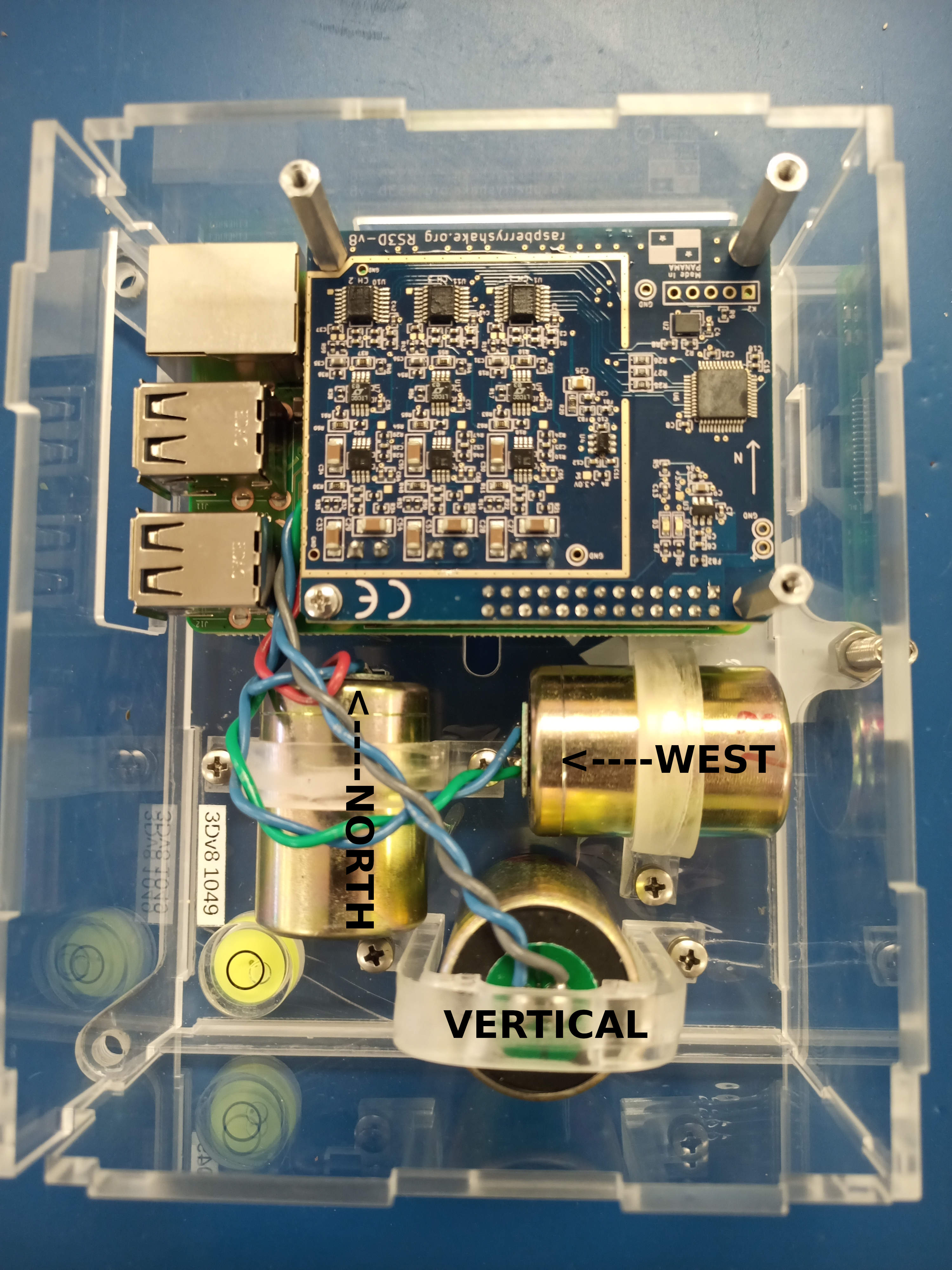
North / South has Red + Blue- wires (North soldered wire side)
The East / West has Green + Blue- wires (West soldered wire side)
The Vertical Z has Gray + Blue- wires
Thanks very much! So the North component is positve polarity in alignment, the the East component is actually the opositite. If west is “positive”, does that mean the wires are attached in opposite polarity, or is this account for on the RS GPIO board or in the response information, given that typical layouts have East as postive (and therefore west would be negative).
So the North component is of positive polarity in alignment, the East component is actually the opposite. A thousand thanks! So the North component is of positive polarity in alignment, the East component is actually the opposite. If west is “positive”, it means that the wires are connected with opposite polarity No
, or this is due to the RS GPIO card No or in the response information, as typical layouts have east as positive (and therefore west would be negative)
Thanks @Albertof007 . Knowing it is handled in the firmware is very helpful!
If there was a circumstance where I had to rototate a North or West sensor by 180 degrees, would it work within the firmware to simply reverse the polarity that the sensor is connected to the RS A/D GPIO Board, or do you see an issue with this?